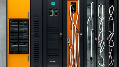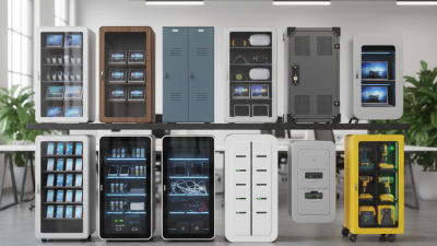
A Charging Cabinet is more than a box filled with power outlets. It is a controlled storage and charging system for batteries, electronic devices, or workplace equipment. Inside, power modules, charging ports, ventilation paths, sensors, and protective controls work together. The cabinet monitors voltage, current, temperature, and charging time. It can also separate devices, reduce cable clutter, and limit risks caused by damaged batteries or poor connections.
Dr. Billy Wu, an electric-vehicle battery researcher at Brunel University London, explains the central principle: “Battery performance depends on how the system is managed, not only on the cells.” This idea gives the Charging Cabinet a wider purpose. It does not simply deliver electricity. It manages the charging environment around each battery. A typical unit may use smart software to balance charging loads, identify abnormal heat, and stop a faulty connection. Some models include fire-resistant compartments, automatic cooling, access control, and usage records. Details matter. A warm adapter pressed against a blocked ventilation opening can change the safety picture quickly.
The working process seems simple, but it is not always predictable. The cabinet receives electrical input, distributes power through internal circuits, and checks each connected device. It then adjusts or interrupts charging when conditions become unsafe. However, no cabinet removes every risk. Users still need proper installation, routine inspection, and compatible equipment. Even advanced monitoring can miss a problem before its symptoms become visible. That limitation deserves attention. Understanding how a Charging Cabinet works helps buyers choose suitable capacity, protection features, and maintenance practices for schools, offices, warehouses, and public facilities.
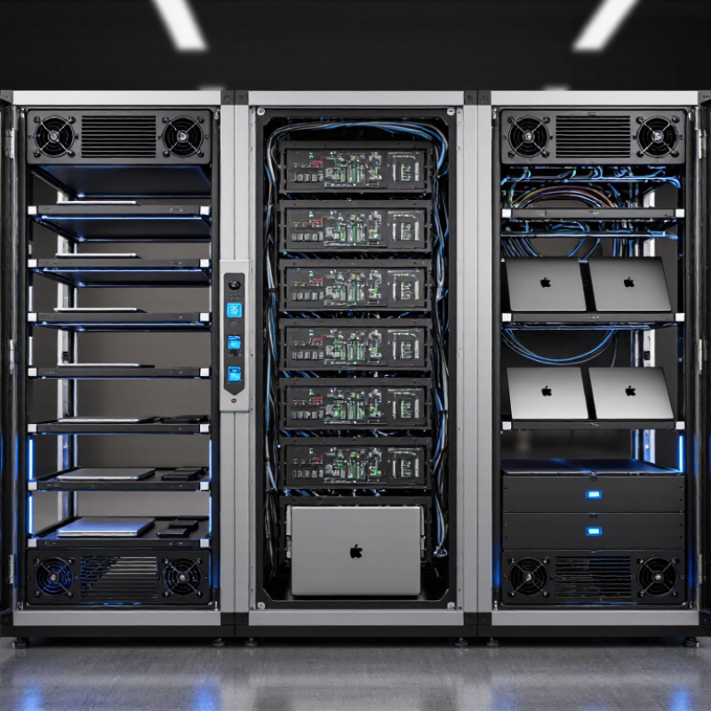
A charging cabinet is an enclosed power-management system for charging several electric vehicles or batteries. It usually contains power modules, circuit protection, cooling equipment, communication controls, and safety sensors. It is not simply a large plug. That distinction matters.
In operation, the cabinet receives alternating current from the building supply. Its power modules convert that electricity into controlled direct current. The cabinet then sends power to one or more charging dispensers. Software balances the load, while sensors monitor temperature, voltage, current, and faults. If conditions become unsafe, the system can reduce output or stop charging. In practical installations, technicians also need clear cable routes, ventilation, and enough service space.
The International Energy Agency reported more than four million public charging points worldwide at the end of 2023. It also recorded over 1.3 million new public points during that year. This growth increases the value of centralized power equipment, especially at busy sites. A cabinet can simplify maintenance and support higher charging capacity without placing every component inside the dispenser. However, the term is not perfectly uniform. Some suppliers use it for multi-device charging storage, while others mean a dedicated DC power unit. Buyers should check the electrical rating, cooling method, protection features, and communication protocol. The U.S. Department of Energy also emphasizes proper equipment listing and installation practices. A cabinet may look tidy, yet poor heat control can quietly shorten component life. That risk deserves more attention.

A charging cabinet is the control center behind several electric-vehicle charging points. It receives grid electricity, manages power, and distributes it safely. The International Energy Agency reported over four million public charging points worldwide at the end of 2023. This rapid expansion makes cabinet reliability increasingly important.
The main component is the enclosure, which protects internal equipment from dust, moisture, and accidental contact. Inside, power distribution units divide incoming electricity between charging modules. AC-to-DC converters regulate voltage for fast charging. A central controller monitors charging status, user commands, and load balance. Communication gateways exchange data with vehicles and management platforms. Safety devices add circuit breakers, fuses, insulation monitoring, surge protection, and emergency shutdown functions. Cooling fans or liquid systems remove heat from high-power modules. Energy meters record consumption for operation and billing. IEC 61851 remains a key reference for conductive charging communication and safety. Yet, field inspections often reveal a weakness: impressive specifications do not guarantee stable performance in heat, dust, or uneven grid conditions.
Tips: Check airflow paths, cable connections, temperature records, and fault logs during maintenance. Leave space around the cabinet. A blocked vent can reduce output quickly. The IEA also notes that charging demand is growing faster in many urban areas, so load management deserves careful testing. Some cabinets appear intelligent, but unclear software alarms can still delay repairs. Verify every warning under real operating conditions.
| Main Component | Primary Function | How It Works | Typical Characteristics | Safety or Maintenance Considerations |
|---|---|---|---|---|
| Enclosure and Charging Shelves | Houses the electrical equipment and provides organized storage for multiple devices or batteries. | Devices are placed in dedicated compartments and connected to internal charging cables or ports. | Usually made from powder-coated steel or other durable, non-combustible materials; shelves may include cable-management openings. | Keep ventilation openings clear, avoid overloading shelves, and inspect the enclosure for damage or corrosion. |
| AC Input and Power Distribution Unit | Receives electricity from the building supply and distributes it to the chargers. | Incoming alternating current passes through an isolator, circuit protection, and internal distribution wiring before reaching individual charging modules. | Designed for the local electrical supply; total input capacity depends on the number and power rating of connected chargers. | Installation should be performed by a qualified electrician. The circuit must be correctly grounded and sized for the expected load. |
| Circuit Breakers and Fuses | Protects wiring and charging equipment from excessive current and short circuits. | A breaker trips or a fuse opens the circuit when current exceeds a safe threshold. | May include one main disconnect and separate branch protection for charging channels or power supplies. | Investigate the cause of repeated trips before resetting a breaker or replacing a fuse. Never bypass protective devices. |
| AC-to-DC Charging Modules | Converts AC power into regulated DC power suitable for rechargeable batteries and electronic devices. | The module controls voltage and current according to the charging requirements of the connected device or battery. | Output voltage, current, connector type, and charging protocol vary according to the equipment being charged. | Use compatible charging modules and cables. Damaged power supplies, exposed conductors, or overheated adapters require immediate service. |
| Charging Cables and Connectors | Transfers electrical power between the charging modules and the devices or batteries. | The connector establishes an electrical connection while the cable carries the controlled charging current. | Cable length, conductor size, connector shape, and current rating must match the application. | Check for frayed insulation, bent pins, loose connections, and heat discoloration. Store cables without sharp bends. |
| Control and Monitoring System | Coordinates charging activity and provides status information. | A controller may detect connected devices, manage charging channels, record faults, and display operating status through indicators or a screen. | Functions can include channel status, charge completion indication, access control, timers, and fault notifications. | Keep firmware and configuration settings controlled by authorized personnel and review fault logs regularly. |
| Battery Management Interface | Supports safe charging of battery packs that require communication or protection monitoring. | The interface may exchange information with a battery management system to regulate charging and identify abnormal conditions. | Common monitored values include battery voltage, temperature, charging current, and state of charge. | Only charge batteries approved for the cabinet. Remove swollen, leaking, damaged, or unusually hot batteries from service. |
| Cooling and Ventilation System | Removes heat generated by power supplies, chargers, and batteries during operation. | Natural convection or fans move warm air away from internal components and bring in cooler air. | The design may include vents, filters, temperature sensors, or thermostatically controlled fans. | Maintain clearance around vents, clean filters when applicable, and stop operation if abnormal heat or fan failure occurs. |
| Temperature Sensors | Detects excessive heat inside the cabinet or near charging equipment. | Sensor readings are sent to the control system, which may reduce charging power, activate cooling, or stop charging. | Sensors are typically positioned near power electronics, batteries, or areas with limited airflow. | Test sensor alarms according to the maintenance schedule and do not obstruct or relocate sensors without authorization. |
| Grounding and Bonding System | Provides a low-resistance path for fault current and helps reduce electric shock risk. | Exposed conductive parts are connected to protective earth so that a fault can activate the electrical protection system. | Includes a protective-earth conductor, bonding points, and properly secured metal connections. | Verify continuity during installation and inspection. Never operate the cabinet with a missing or damaged earth connection. |
| Door Lock, Access Control, and Emergency Stop | Restricts unauthorized access and allows charging to be stopped quickly during an emergency. | A key, electronic lock, or access credential controls entry, while the emergency-stop device disconnects or disables charging. | The emergency stop is generally designed for rapid manual activation and clear visual identification. | Keep the emergency-stop control unobstructed, test it periodically, and reset it only after the hazard has been assessed. |
| Status Indicators and User Interface | Communicates power, charging, completion, warning, and fault conditions to users. | LED indicators, displays, or audible alarms present information received from the control and monitoring system. | Clear labels and consistent color coding help users identify operating conditions quickly. | Keep labels readable and report conflicting indicators, unexplained alarms, or display failures. |
A charging cabinet combines power distribution, charging control, device storage, thermal management, and electrical protection in one organized enclosure. Its exact configuration depends on the number, type, and charging requirements of the devices or batteries it supports.
A charging cabinet stores and powers several electronic devices in one controlled enclosure. It may hold tablets, laptops, tools, or removable battery packs. Its internal power strip connects to a protected electrical supply. Adjustable shelves and cable openings keep chargers separated and easier to inspect.
A user opens the door and places each device in an assigned slot. The charging cable connects to the device, while the adapter remains inside the cabinet. When the cabinet receives power, its distribution system sends electricity through each connected charger. Some models charge all ports together. Others divide power according to battery demand.
The cabinet may monitor temperature, current, and charging time. If heat rises too much, ventilation fans can move warm air away from the adapters. A control circuit may reduce or stop power when a fault appears. The door can also limit access during charging. Small details matter here. Blocked vents, damaged cables, or overloaded outlets can create real problems. A careful operator checks connections before closing the door and keeps the cabinet away from moisture and heat sources.
The process is not perfectly automatic. Battery indicators can be inaccurate, and a cabinet may not detect every damaged adapter. Regular inspection remains necessary. A trained technician should test grounding, airflow, socket condition, and emergency controls according to the equipment instructions. In practice, a clear charging schedule also prevents devices from being left connected longer than needed.
A charging cabinet stores and powers multiple portable devices in separate compartments. Its internal power system distributes electricity through protected outlets or charging cables. Fans or ventilation gaps help release heat during operation. This matters when many batteries charge at the same time.
Most cabinets hold tablets, laptops, smartphones, e-readers, handheld scanners, and wireless communication devices. Some models also accommodate cameras, headsets, or compact medical electronics. Each compartment should provide enough space for the device and its cable.
A tightly packed shelf can block airflow and damage connectors. Small devices fit easily. Larger laptops need deeper slots and stronger cable management.
Compatibility requires careful checking. The cabinet must support the device’s charging standard, voltage range, and power demand. Do not assume every USB port charges every device efficiently. Technicians should inspect cables, sockets, and ventilation before daily use. I have seen poor cable labeling cause unnecessary delays and uneven charging. That small detail deserves more attention. Users should remove swollen or unusually hot batteries and arrange professional inspection. A cabinet is useful, but it cannot correct damaged batteries, unsuitable adapters, or overloaded circuits.
A charging cabinet stores and powers several rechargeable devices in one controlled enclosure. It usually contains power outlets, charging cables, ventilation openings, and monitoring controls. When a device connects, the cabinet supplies electricity through its charging circuit. Sensors can detect heat, current changes, and charging progress. The system may then reduce power or stop charging automatically.
Safety features are the cabinet’s most important function. Temperature sensors watch for unusual heat around batteries and power components. Overcurrent protection helps prevent damaged cables from drawing excessive electricity. Surge protection can reduce risks caused by unstable power. Many cabinets use fire-resistant materials and separate charging spaces, limiting heat transfer between devices. Ventilation removes built-up warmth, although vents must remain clear. A lockable door also helps prevent unauthorized access and accidental cable damage. Some models provide audible alarms when smoke, overheating, or electrical faults appear. These features improve safety, but they cannot correct every battery defect.
Tips: Place the cabinet on a stable, dry surface with open airflow. Inspect cables for cuts, crushed sections, or loose plugs before charging. Do not pack devices tightly against vents. Follow the cabinet’s rated capacity and charging instructions. Keep paper, fabric, and other flammable materials away. Regular inspections matter, because a quiet cabinet can still hide a failing connection. No protection system is perfect; replacing damaged batteries and reporting unusual smells remain essential precautions.
A charging cabinet is an enclosed electrical system that distributes power to multiple devices or batteries while organizing cables and controlling charging conditions. Typical safety designs combine electrical protection, thermal monitoring, fire protection, and controlled user access. The chart groups commonly used safety functions by protection category; the values represent the number of representative functions listed in each category, not a certification rating.